STRUX® 90/40 Concrete Fibers ASTM C1399 vs. ASTM C1609 – TB-1205

How are fibers tested and evaluated in concrete?
There are two ASTM flexural test procedures used to evaluate the performance of “macro” synthetic fibers, ASTM C1399 and ASTM C1609. Both are commonly used but there are some major differences between them and where they should be specified. ASTM C1399 is the more commonly used and specified, but this test has certain limitations as compared to ASTM C1609.
What is ASTM C1399?
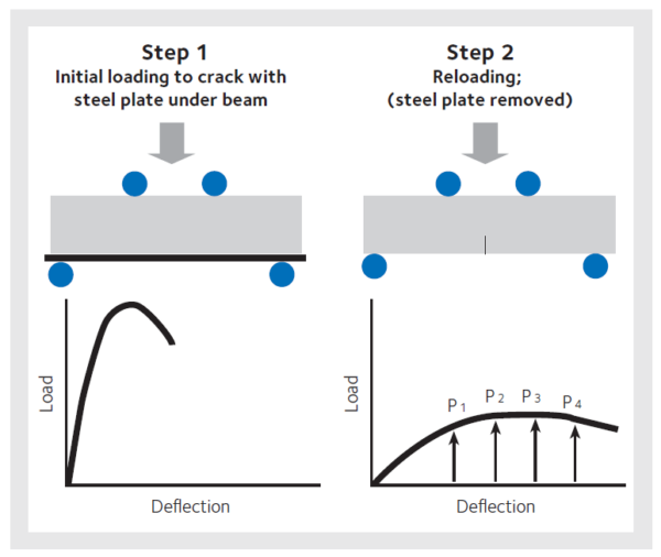
This test method covers the determination of the average residual strength (ARS) of a fiber-reinforced concrete test beam supported by a steel plate underneath the entire length. The flexural beam is initially cracked from an applied load up to a deflection of 0.008 in. (0.2 mm). The steel plate is then removed and the post-crack deflections and loads are measured and recorded during the test up to a final deflection of 0.05 in. (1.25 mm). The ARS is computed using loads at specified beam deflections that are obtained during the test. This test provides the data needed to obtain the portion of the load-deflection curve beyond which a significant amount of cracking damage has occurred. It also provides an average measure of post-cracking or residual strength obtained by the use of fiber-reinforcement.
What applications should ASTM C1399 be specified for and why?
Since ASTM C1399 only allows the use of 4 in. x 4 in. x 14 in. (100 mm x 100 mm x 350 mm) beams, GCP recommends it to be used for concrete applications of 4 inches thickness or less if the fiber length is less than or equal to 1.5 in. (40 mm). Therefore applications such as precast, thin overlays, whitetoppings, and slab-on-ground with thicknesses 4 inches or less be specified by ASTM C1399.
Why?
- Testing in our labs, pre-cast production, and thin overlays have shown there is a tendency for fibers to have preferential alignment providing good results. However this cannot be related to concrete members with a thickness greater than 4 inches.
- ASTM C1399 recommends that for tests of fiber-reinforced concrete containing relatively rigid or stiff fibers of length greater than 1.5 in. (40 mm), the use of sawed beams cut from samples with an initial width and depth of at least 3 times the length of the fiber is recommended to minimize effects of fiber orientation. This requires special cutting equipment with a diamond saw and creates another procedural step for the concrete lab and is rarely performed.
- With ASTM C1399 the flexural strength of the fiber-reinforced concrete cannot be obtained. In order to determine the flexural strength an additional test such as ASTM C78 needs to be performed.
- The fracture behavior of fiber reinforced concrete at small crack openings cannot be determined using ASTM C1399 since the ARS value is only an average load value taken at deflections equal and greater than 0.02 in. (0.5 mm) of deflection.
Figure 1
What is ASTM C1609?
This test method evaluates the flexural performance of fiber-reinforced concrete using parameters derived from the load-deflection curve. This is obtained by testing a simply supported beam under third-point loading using a closed-loop, servo-controlled testing system. Without this closed-loop control system, stable crack propagation after peak is very unlikely to be achieved. (Unlike ASTM C1399, a steel plate is NOT used for achieving controlled cracking of concrete.)
This test method provides for the determination of first-peak and peak loads and the corresponding stresses calculated by inserting them in the formula for modulus of rupture.
It also requires determination of residual loads at specified deflections, and the corresponding residual flexural strength (see NOTE 1). At the option of the specifier, it provides for determination of specimen toughness based on the area under the load-deflection curve up to a prescribed deflection (see NOTE 2).
What applications should ASTM C1609 be specified for and why?
- The larger beam allows the use of macro fibers up to 2.5 in. (65 mm) in length. This will accommodate for the majority of macro fibers on the market that have lengths between 1.5 to 2.5 in. (38 to 65 mm).
- The potential preferential alignment of fibers is now reduced and a more random distribution of fibers both horizontally, vertically and diagonally will occur similar to “real life” concrete with fibers.
To summarize the differences between ASTM C1399 versus ASTM C1609 with respect to preferential fiber alignment of small versus large beams, Figure 3 represents STRUX® 90/40 cast from identical concrete placed in small and large beams and then tested.
Tables 1 and 2 represents the ARS values (ASTM C1399) and fe3 values (ASTM C1609, formerly ASTM C1018-97) for a variety of addition rates and concrete strengths. The values in the tables are a result from over 500 beam tests done in our Research & Development Laboratory.
Figure 2
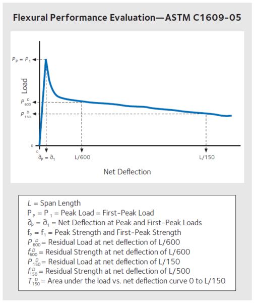
Figure 3
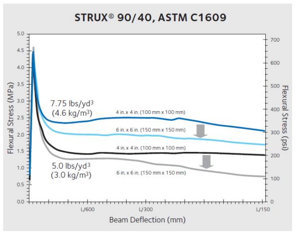
Table 1 – ARS values measured according to ASTM C1399-07
| STRUX® 90/40 lbs/yd3 | Cylinder Compressive Strength (psi) | ||||||
| 3,000 | 3,500 | 4,000 | 4,500 | 5,000 | 5,500 | 6,000 | |
| 3.0 | 95 | 110 | – | – | – | – | – |
| 3.5 | 125 | 140 | 150 | 160 | 175 | – | – |
| 4.0 | 150 | 165 | 175 | 185 | 200 | 210 | 220 |
| 4.5 | 175 | 185 | 195 | 210 | 220 | 230 | 245 |
| 5.0 | 195 | 205 | 215 | 230 | 240 | 250 | 250 |
| 5.5 | 215 | 225 | 235 | 245 | 255 | 270 | 280 |
| 6.0 | 230 | 240 | 250 | 260 | 275 | 285 | 295 |
| 6.5 | 245 | 255 | 265 | 275 | 285 | 300 | 320 |
| 7.0 | 260 | 270 | 280 | 290 | 300 | 310 | 320 |
| 7.5 | 270 | 280 | 295 | 305 | 315 | 325 | 335 |
Table 2 – Fe3 values measured according to JSCE* (JCI-SF4)
| STRUX® 90/40 lbs/yd3 | Cylinder Compressive Strength (psi) | ||||||
| 3,000 | 3,500 | 4,000 | 4,500 | 5,000 | 5,500 | 6,000 | |
| 3.0 | 95 | 105 | – | – | – | – | – |
| 3.5 | 105 | 115 | 125 | 135 | 140 | – | – |
| 4.0 | 120 | 130 | 140 | 150 | 155 | 165 | 175 |
| 4.5 | 135 | 145 | 155 | 165 | 170 | 180 | 190 |
| 5.0 | 150 | 160 | 170 | 180 | 185 | 195 | 205 |
| 5.5 | 165 | 175 | 185 | 195 | 200 | 210 | 220 |
| 6.0 | 180 | 190 | 200 | 210 | 215 | 225 | 235 |
| 6.5 | 195 | 205 | 215 | 225 | 235 | 240 | 250 |
| 7.0 | 210 | 220 | 230 | 240 | 250 | 255 | 265 |
| 7.5 | 225 | 235 | 245 | 255 | 265 | 270 | 280 |
Conclusion
For basic slab-on-ground and pre-cast applications, refer to the recommendations for each ASTM test and tables when specifying ARS or fe3 values. In addition, we have developed a slab-on-ground design software (STRUX® 90/40 SDS™) that has the capability to assist with a variety of applied loading on slabs from wheel loads, post loads, racking systems, walls loads or uniform loading. It calculates an addition rate of STRUX® 90/40 for edge, center, or free-edge loading cases obtained from details such as concrete strength (f’c), modulus of sub-grade reaction (k-value), joint spacing, and the coefficient of friction. The analysis will provide a 25-page report showing the most cost-effective thickness of concrete and addition rate of STRUX® 90/40 using the Yield Line theory backing up the calculations accepted by Chapter 10 of ACI 360.